

SCREW PILE LOAD CAPACITY CALCULATION METHOD
(Indirect Estimation via Hydraulic System Pressure)
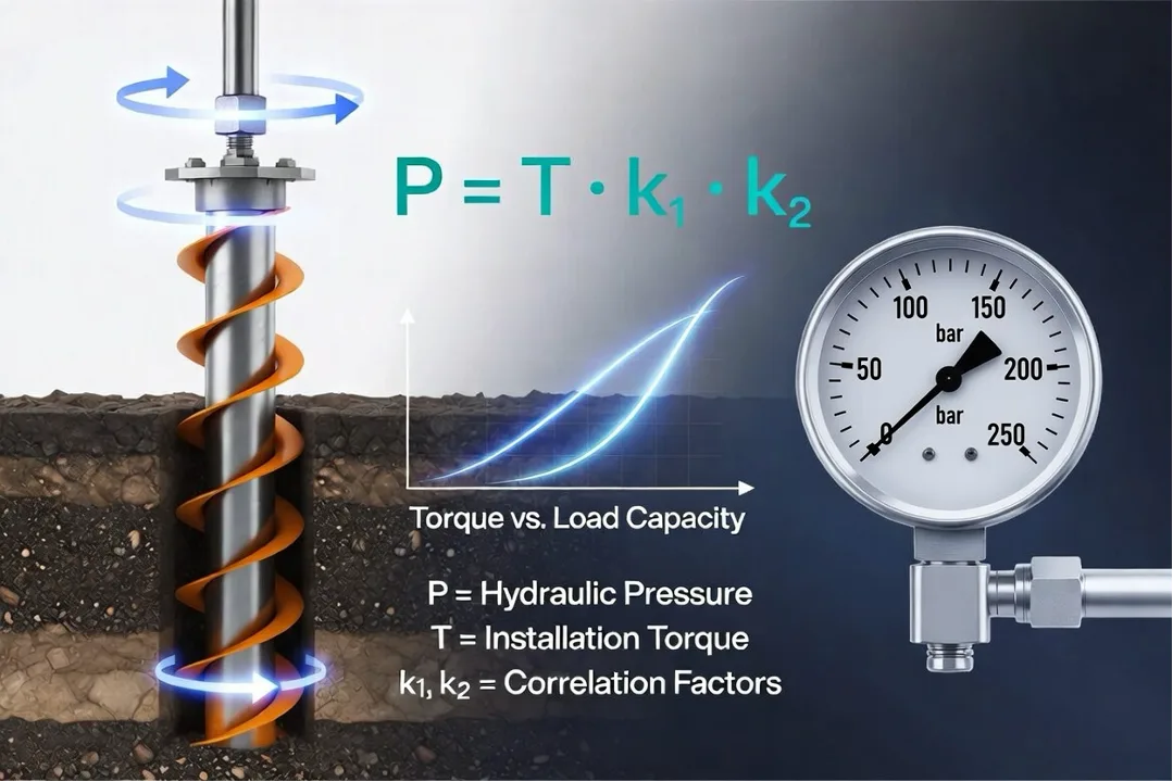
This is the most reliable method when a torque meter indicator is unavailable. Since you are using a hydraulic driver, the output torque is directly proportional to the oil pressure in the system.
Step-by-Step Procedure:
- Record Final Pressure: At the final stage of installation (when the pile reaches its target depth), record the pressure indicated on pressure gauge of the hydraulic power pack.
– Example: The gauge shows 120 bar.
- Convert Pressure to Torque: Use the performance table specific to your hydraulic driver to find the corresponding torque.
– Example: According to the 11000 Nm driver data, 120 bar equals 8255 Nm of torque.
Table 1. Torque vs. Operating Pressure (FALCON 11000 Nm, CLAW 11000 Nm, COUGAR 11000 Nm)
| Pressure (bar) | Torque M (Nm) |
| 10 | 688 |
| 20 | 1 375 |
| 30 | 2 065 |
| 40 | 2 750 |
| 50 | 3 438 |
| 60 | 4 125 |
| 70 | 4 813 |
| 80 | 5 500 |
| 90 | 6 188 |
| 100 | 6 875 |
| 110 | 7 563 |
| 120 | 8 255 |
| 130 | 8 938 |
| 140 | 9 625 |
| 150 | 10 313 |
| 160 | 11 000 |
| 170 | 11 688 |
| 180 | 12 375 |
| 190 | 13 063 |
| 200 | 13 750 |
- Apply the Correlation Formula: The ultimate loading capacity of installed screw pile is calculated using the empirical correlation formula:
P = T × k1 × k2, where:
– P – Ultimate Loading Capacity of installed screw pile (kg).
– T – Installation Torque converted to kg·m (Т=Torque M (Nm)/9.8 м/с²).
– k1 – Coefficient (Screw pile tube diameter Correlation Factor)
– k2 – Coefficient (Soil Type Correlation Factor)
Table 2. k1 – Coefficient (Screw pile tube diameter Correlation Factor)
| Screw pile tube diameter (mm) | k1 | Remarks | ||
| 57-76 | 10-11 | High efficiency in torque-to-load transfer | ||
| 89 | 9 | Industry standard medium size. | ||
| 108 | 8.0-8.5 | Most common size for residential/light industrial. | ||
| 114-133 | 7.0-8.0 | Significant increase in shaft skin friction. | ||
| 159 | 6.0-7.0 | High energy loss due to shaft-to-soil contact. | ||
| 219 | 5.0 | Requires high-torque heavy hydraulic machinery (11000 Nm and more). | ||
| Table 3. k2 – Coefficient (Soil Type Correlation Factor) | ||||
| Soil Type | k2 | Description | ||
| Stiff Clay / Hard Loam | 1.0 (Baseline) | Dry, difficult to excavate | ||
| Plastic Clay / Wet Loam | 1.1 (Higher efficiency) | Sticky, soft consistency | ||
| Dense Sand | 0.85-0.9 (Risk of torque overestimation) | Coarse, dry, high friction | ||
| Pine Saturated Sand / Silt | 0.8 (Torque exists, but bearing is low) | Water-logged or “quicksand” | ||
| Peat / Organic Silt | Not Applicable (Pile must penetrate through to solid strata) | Highly organic deposits | ||
Important Note: In practice, contractors apply a Factor of Safety (FoS), typically 1.25 to 1.5. If the calculated ultimate capacity is 7.8 tons, the safe allowable load should be limited to approximately 5.2 – 6.2 tons.
Step-by-Step Calculation Example (Cheat Sheet)
Scenario: A contractor installs a 108 mm pile in Sandy soil. The gauge shows the pressure 120 bar.
Step 1. Determine Torque. Look the Table 1: 120 bar = 8250 Nm.
Step 2. Convert to kg·m: 8250 Нм / 9.8 м/с²= 842 kg·m.
Step 3. Select k1 and k2. Look the Table 2 and the Table 3:
– Coefficient k1: Screw pile tube diameter 108 mm = 8.0
– Coefficient k2: Dense Sand = 0.85-0.9
Step 4. Calculate Ultimate Loading Capacity: 842 kg·m × 8.0 × 0.9 = (6062 kg or 6.0 Metric Tons).
Step 5. Apply Factor of Safety (FoS = 1.25): 6062 kg / 1.25 = (4849 kg or 4.8 Metric Tons).
Final Verdict: At a 120-bar installation pressure, the pile provides a Safe Allowable Load of 4.8 Tons.
Respectly yours, IM Team.