

Design of a foundation on screw piles (helical piles, ground screws).
A screw pile is an anchoring foundation element whose performance depends less on bearing area and more on the soil shear resistance in the blade zone. Errors at the design stage lead to uneven settlements and deformation of the foundation geometry.
- Geotechnical analysis
Using “averaged” regional reference data is unacceptable. The design begins with determination of the soil physical‑mechanical properties.
– Assessment method: The optimal methods are static probing (CPT) or a trial screwing with recording of torque at different depths.
– Investigation depth: Should be at least 2 m below the planned depth of blade penetration.
– What to look for: Presence of peat lenses, groundwater level (GWL), and — most importantly — identification of the bearing layer. The blade must be anchored in dense soil below the frost penetration depth by at least 0.5–1.0 m.
- Load collection and bearing capacity calculation
Design is performed for the first and second limit states.
– Load formula:

- Pile structure: how to prevent corrosion failure
A typical mistake is choosing the minimum wall thickness to save cost.
– Wall thickness: For residential buildings the minimum acceptable pipe wall thickness is 4 mm, blades — 5 mm. Account for a “corrosion allowance”: corrosion rate in non‑aggressive soils is about 0.03–0.05 mm/year per side.
– Anti‑corrosion coating: Hot‑dip galvanizing is preferred. Epoxy coatings are effective only if the soil contains no abrasives (stones) that can strip the layer during screwing.
– Grouting/concreting the shaft: Mandatory. Cement‑sand mix or concrete inside the shaft displaces air and prevents internal corrosion. A pile without internal concreting is a temporary structure.
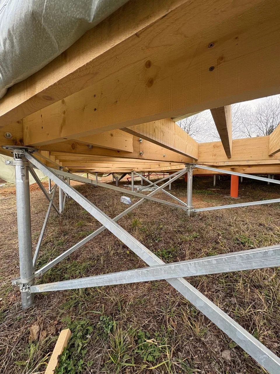
- Field geometry and lateral stability
It is important to account for screw piles’ behavior under transverse bending (lateral loads).
– Plinth height: If the pile projection above ground exceeds 600 mm, horizontal or diagonal bracing (struts) of profile pipe or angle must be installed. This creates a rigid spatial frame.
– Pile spacing: Should not exceed 2.5–3.0 m, even if bearing capacity would allow larger spacing. The limitation is dictated by the stiffness of the grillage (tie beams or channel) against deflection.
- Control points during execution (Work Production Plan)
The design must include requirements for as‑built documentation:
1) Torque control: Record the installation torque at final penetration. If the torque “drops off” — the pile must be extended to reach dense layers.
2) Verticality: Allowable deviation — no more than 2°. Ignoring this leads to a bending moment the pile may not be designed to resist.
3) Horizontal: Piles are cut to the leveling line. Leveling by backing a pile out is forbidden — this loosens the soil beneath the blade and will cause immediate settlement.
- Summary: “Anti‑Fail” Checklist
- Pile not bearing: Design torque not reached — the house may “float away” in spring.
- Saving on diameter: Using an 89 mm pile instead of a 108 mm where the load exceeds 3 tonnes per point.
- Missing pile caps: Or tack‑welding them. The weld must be sealed (watertight)!
- Ignoring frost heave: If the blade sits in a frost‑susceptible layer, the foundation will heave every winter.
Conclusion: A screw‑pile foundation is a rigid “screw‑soil” system. If the load is transferred to the design soil horizon and the metal is protected from corrosion, the foundation service life will be 70+ years. Deviations from the regulations (under‑torquing, thin pile wall, lack of concreting) can significantly shorten that life.
Contact us and we will reveal the secrets of strong screw pile foundations and provide your business with reliable equipment for installing helical piles!